How to Control Servo Motor with Assembly Code: A Step-by-Step Guide
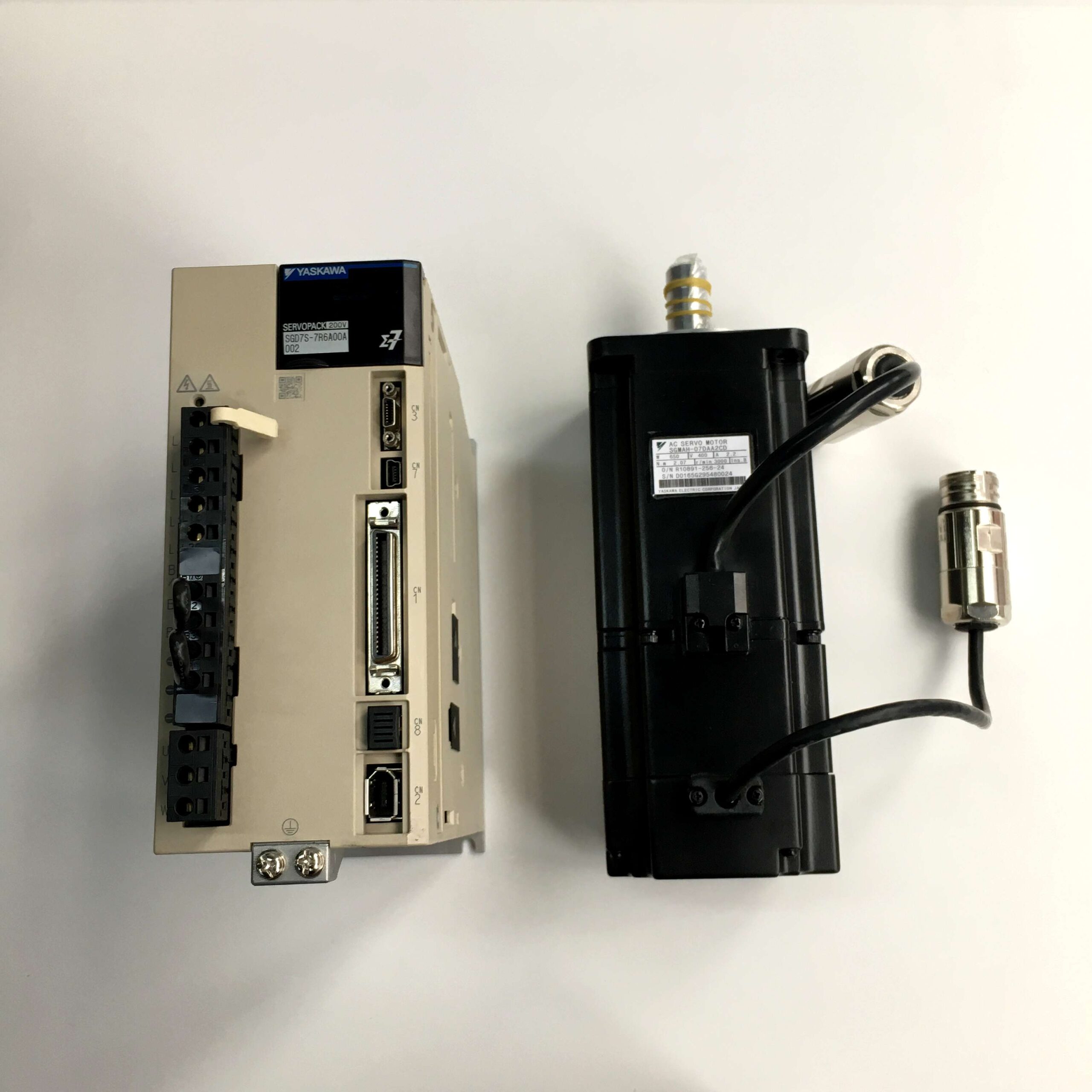
Servo motors are widely used in various industries for their precision control capabilities, especially in robotics, manufacturing, and automation. Controlling a servo motor with assembly code can seem daunting, but it’s an essential skill for developers looking to achieve maximum flexibility and performance in embedded systems. This guide will take you through all the steps necessary to control a servo motor using assembly language, with detailed explanations of each aspect.
Basics of Assembly Language for Servo Motor Control
Why Use Assembly Code?
Assembly language is often used for servo motor control because it allows direct manipulation of microcontroller registers and memory, offering low-level access that results in highly efficient control. Some of the benefits of using assembly code include:
- Precise Timing Control: Servo motors need precise control signals, and assembly language offers a level of precision that is difficult to achieve with higher-level languages.
- Optimized Performance: Assembly code can produce optimized routines for speed and size, essential for embedded systems with limited resources.
When writing assembly code, you should understand your microcontroller architecture, specifically how timers and interrupts work. Microcontrollers like the AVR or PIC series are popular choices for such projects.
Components Needed
To get started, you will need:
- A servo motor (either standard or continuous rotation).
- A microcontroller (such as ATmega328 or PIC16F877A).
- A power supply matching the servo’s power requirements.
- A breadboard for prototyping.
- Connecting wires and resistors as needed.
Additionally, check our Panasonic Servo Motors MINAS A5 for more robust industrial applications.
Writing Assembly Code for Servo Control
Setting Up the PWM Signal
The key to controlling a servo motor is generating a PWM signal of appropriate frequency and duty cycle. For most standard servos, a PWM frequency of 50 Hz (20 ms period) is required, with a pulse width between 1 ms and 2 ms for the 0° and 180° positions respectively.
The following steps outline how to generate the necessary PWM signal using assembly code:
- Configure Timer Module: Use the timer module in your microcontroller to generate a PWM signal. Typically, an 8-bit timer or 16-bit timer is used to achieve the required accuracy.
   ; Pseudo-Assembly Code Example for AVR Microcontroller
   LDI R16, 0x00        ; Load initial value
   OUT TCCR1A, R16      ; Set Timer1 Control Register A to zero
   LDI R16, 0b10101000  ; Set Timer1 in Fast PWM mode, non-inverted
OUT TCCR1B, R16- Set PWM Duty Cycle: The duty cycle determines the width of the pulse, which, in turn, defines the angle of the servo motor. For 90°, the pulse width is typically 1.5 ms.
   ; Set duty cycle for 90-degree position
   LDI R16, 0x7D        ; Load compare value
OUT OCR1A, R16 ; Output compare register set to generate 1.5 ms pulse- Initialize Ports: Set the microcontroller pins connected to the servo as output.
   LDI R16, 0b00000010  ; Set pin PD1 as output
   OUT DDRD, R16        ; Data Direction Register D
Using Interrupts for Precise Control
Using timer interrupts helps maintain the necessary timing requirements without manually monitoring each cycle. By configuring an interrupt service routine (ISR), you can handle different motor tasks precisely while the main program handles other functionalities.
- Enable Timer Interrupts: Configure the timer interrupt to trigger every 20 ms.
  SEI                ; Set Global Interrupt Enable
  LDI R16, 0x02      ; Enable Timer1 Output Compare Interrupt
OUT TIMSK1, R16- Write the ISR: The ISR will handle the generation of PWM signals needed to control the servo.
  ISR(TIMER1_COMPA_vect)
  LDI R16, PWM_VALUE   ; Load the required pulse width
  OUT OCR1A, R16       ; Output to control the pulse duration
  RETI                 ; Return from interrupt
Practical Applications of Assembly Code in Servo Motor Control
1. Robotics
In robotics, assembly code helps in providing real-time speed and position control for servo motors used in robotic arms. This is crucial when robots need to perform repetitive tasks with high precision.
- Pick and Place Systems: Assembly language allows precise timing control required for pick and place operations where the robotic arm must quickly respond to positional commands.
2. Automated Production Lines
Assembly code is also used in automated production lines where servo motors need to be synchronized with sensors and other actuators to ensure the correct operation. Using direct control over timers and ports ensures that there are minimal delays in the system.
- Conveyor Systems: Servo motors drive conveyor belts with precisely controlled speed, which assembly programming can optimize for efficiency.
For servo motors best suited for these types of applications, consider our Panasonic Servo Motor MINAS A5 2KW.
Debugging and Testing Your Assembly Code
Common Issues and Solutions
- Timing Issues: If the servo is jittery, ensure the PWM frequency is correct, and the timer is configured properly.
- Motor Not Moving: Double-check the connections and power supply. Ensure that the servo enable pin is set correctly in the assembly code.
- Overheating: This could indicate incorrect PWM duty cycle settings leading to continuous movement beyond the intended range.
Tools for Debugging
- Use a logic analyzer to inspect the PWM signal and verify its timing.
- Simulation software like Proteus can be used to simulate the microcontroller and servo motor setup before physical implementation.
Conclusion
Controlling a servo motor with assembly code provides high precision and efficiency, especially for embedded systems and robotics. While it requires a deeper understanding of microcontroller architecture and careful handling of timers and interrupts, the control and performance gained are significant. By following this guide, you can confidently set up and write the assembly code required to generate the PWM signals needed to control your servo motor effectively.
For a wide variety of servo motors and technical support, visit our Servo Motor Store. We provide solutions for every industrial and robotics application, from basic to advanced.
FAQs
1. What is the advantage of using assembly language for servo motor control?
Assembly language allows for precise control of motor signals and direct hardware manipulation, which can improve system performance and reduce latency.
2. How do I set the PWM duty cycle for a 180° position?
You need to set the pulse width to around 2 ms, corresponding to a 100% duty cycle in a 50 Hz PWM signal.
3. What microcontrollers are commonly used for servo motor control?
Popular microcontrollers include the AVR series (like ATmega328) and PIC series. They both have timers that are well-suited for generating PWM signals.
4. Can I use assembly code for controlling multiple servos?
Yes, but you will need to carefully configure multiple PWM outputs and possibly use additional timers or external multiplexing circuits.
5. How do I handle jitter in my servo motor control?
Jitter is often caused by interrupt timing issues or noise. Ensure your PWM signal is stable by adjusting the timer settings and using capacitors for noise filtering. Using a dedicated servo controller can also help reduce jitter.
6. How can I debug my servo motor control assembly code effectively?
Use logic analyzers to verify your PWM signals and check whether the pulse width matches your intended control. Additionally, consider simulating your assembly code with microcontroller simulators before actual hardware implementation.
Feel free to reach out if you have further questions or need additional guidance on selecting the right servo motor for your project!
