How to Control Servo Motor with Assembly Language: A Step-by-Step Guide
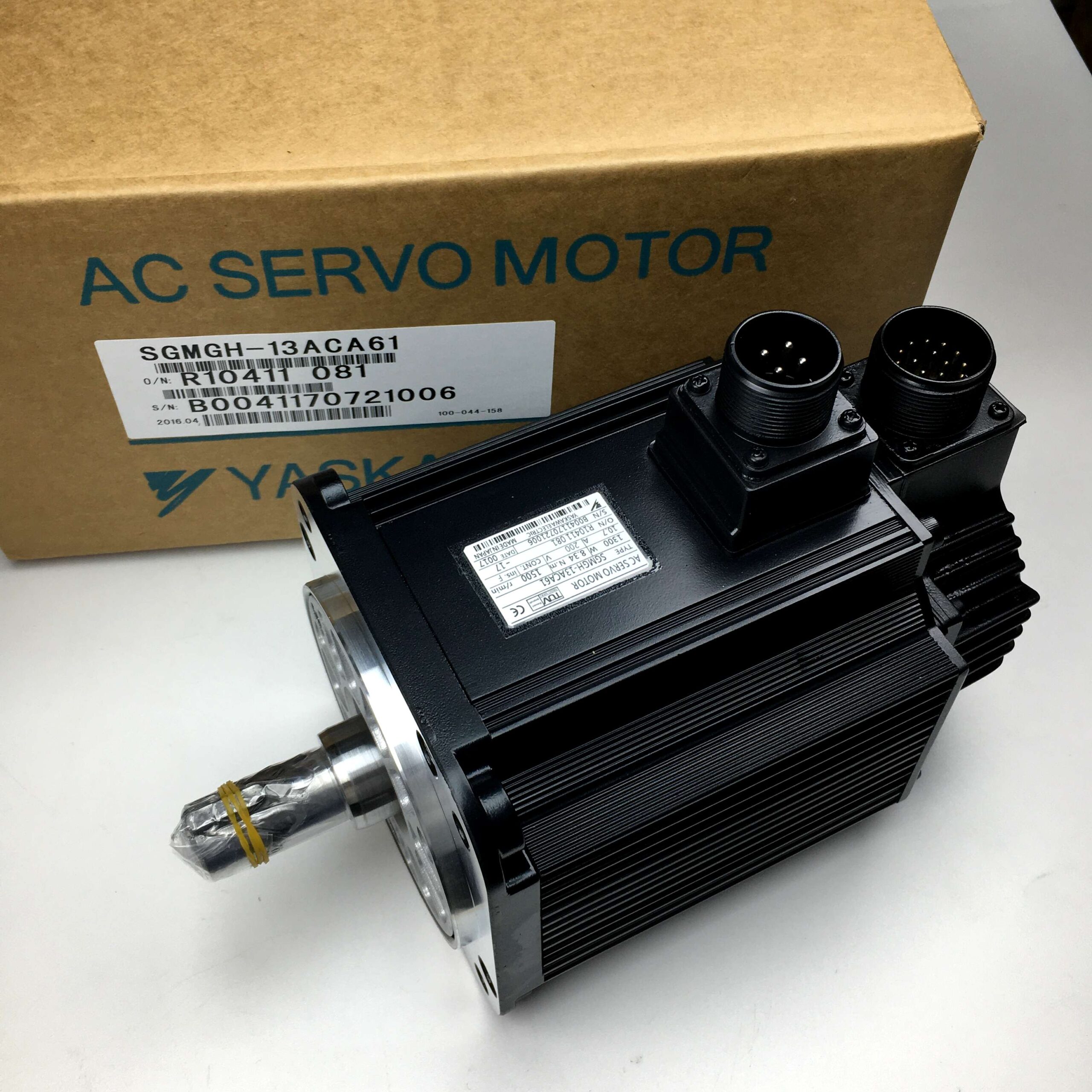
If you are interested in precise control of a servo motor using low-level programming, understanding how to control a servo motor with assembly language can provide exceptional precision and a deep understanding of both the hardware and software aspects. This guide aims to walk you through the process of controlling a servo motor using assembly language, and we’ll cover everything you need to know, from understanding the basic components to practical implementation examples.
Understanding Assembly Language Basics
What is Assembly Language?
Assembly language is a low-level programming language that allows programmers to write code that directly manipulates the hardware. Unlike high-level languages, assembly language provides a closer connection to the actual operations of the microcontroller, allowing for more efficient and precise control of hardware components like a servo motor.
Features of Assembly Language:
- Direct Hardware Access: It offers more direct control over CPU operations, memory, and peripherals.
- Efficiency: Assembly code is typically faster and uses less memory compared to high-level languages.
- Complexity: Writing in assembly can be challenging due to its complexity and the requirement to manage all aspects of hardware control.
“Assembly language is like being the conductor of an orchestra, ensuring every component plays exactly on cue to achieve harmony.”
Why Control a Servo Motor with Assembly Language?
Controlling a servo motor using assembly language gives you complete control over the motor’s operations, providing greater precision and customization for complex applications. This can be crucial for industrial robotics or custom automation systems where efficiency and control are paramount.
Setting Up the Environment for Servo Motor Control
Required Components
To successfully control a servo motor using assembly language, you will need:
- Microcontroller: The hardware that will run the assembly code. Popular options include AVR, PIC, or ARM-based microcontrollers.
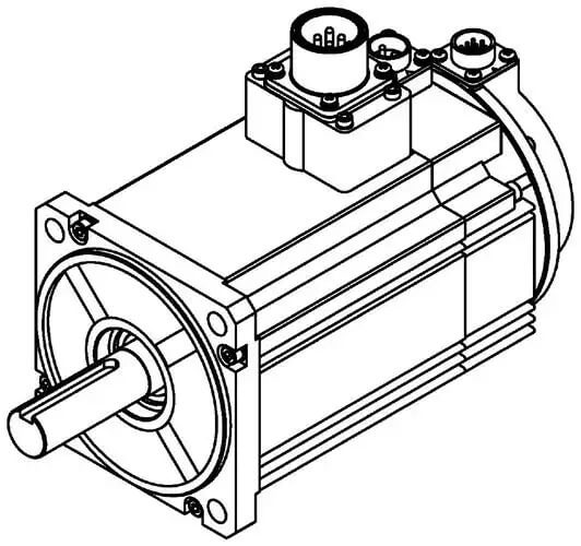
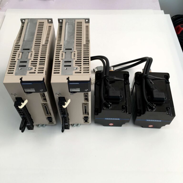
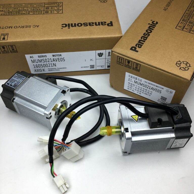
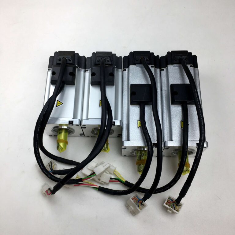
- Servo Motor: Such as Panasonic MINAS A5.
- Power Supply: A stable power source to power the motor.
- Breadboard and Wires: For prototyping and connecting components.
- Assembly Programming Software: Tools like MPLAB for PIC microcontrollers or AVR Studio for AVR microcontrollers.
Setting Up the Microcontroller for Servo Motor Control
- Pin Configuration: Identify and configure the correct output pins on the microcontroller to send signals to the servo motor. Typically, the PWM (Pulse Width Modulation) pin is used for sending control signals.
- Voltage Requirements: Verify the voltage requirements of both the servo motor and microcontroller, ensuring the correct voltage levels are supplied to prevent damage.
- Clock Frequency: Set the appropriate clock frequency in your assembly code to control the timing of signals sent to the servo motor.
Note: Setting the right clock frequency is crucial as it determines the precision of the servo movements.
Writing Assembly Code to Control a Servo Motor
Understanding Pulse Width Modulation (PWM)
Servo motors are controlled by Pulse Width Modulation (PWM). The position of the servo is determined by the duration of the pulse. A typical PWM signal to control a servo motor has:
- Frequency: Generally around 50 Hz.
- Pulse Width: Between 1 ms to 2 ms, corresponding to the minimum and maximum angles of the servo.
| Pulse Width | Position |
|---|---|
| 1 ms | -90 degrees |
| 1.5 ms | Neutral (0 degrees) |
| 2 ms | +90 degrees |
“Understanding PWM is the key to precise servo control, especially when using assembly language to define exact timings.”
Assembly Code Structure
An example outline of the assembly code for controlling a servo motor is as follows:
- Initialization: Set up the microcontroller pins and timer configuration.
- PWM Signal Generation: Write code to generate PWM signals based on desired servo positions.
- Looping for Continuous Control: Use a loop structure to continuously adjust the PWM width to move the servo motor as required.
Below is a sample code for controlling a servo motor connected to an AVR microcontroller:
; Initialize ports and set PWM signal
.equ SERVO_PIN = 0b00000001 ; Set pin 0 as servo control pin
ldi r16, SERVO_PIN           ; Load servo pin value
out DDRB, r16                ; Set pin as output

; Set up timer for PWM generation
ldi r16, (1 << WGM01) | (1 << WGM00) ; Fast PWM mode
out TCCR0A, r16
ldi r16, (1 << CS01)                 ; Prescaler set to 8
out TCCR0B, r16

; Generate PWM pulse for 1.5 ms
ldi r16, 128       ; Load value for 1.5 ms pulse
out OCR0A, r16     ; Set Output Compare Register for PWM

loop:
rjmp loop          ; Keep looping to maintain the servo position
Code Explanation
- Pin Setup: Configures the appropriate pin on the microcontroller to serve as the output pin for controlling the servo motor.
- PWM Timer Setup: Sets up the timer in fast PWM mode, and a prescaler value is used to adjust the clock speed.
- Pulse Generation: The
OCR0Aregister value is modified to change the pulse width, which corresponds to the servo’s position.
Tip: The value loaded into
OCR0Adetermines the servo’s position, making it essential to adjust this value based on the specific requirements of your application.
Practical Applications of Servo Motor Control Using Assembly Language
Example 1: Robotic Arm Control
One practical application of controlling a servo motor with assembly language is in a robotic arm. Assembly language can provide precise movements essential for robotics.
Steps to Implement:
- Write different PWM sequences for each joint of the robotic arm.
- Synchronize the PWM signals to achieve coordinated movements of the arm joints.
This precision is ideal for tasks such as assembling components on a production line, where exact positioning is required.
Example 2: Home Automation Systems
Another useful application is home automation, such as controlling blinds or doors using a servo motor. By writing assembly language code, users can have direct and reliable control of the motors that open and close the blinds.
Steps to Implement:
- Set up a microcontroller connected to a sensor (such as a light sensor).
- Use assembly language to generate PWM signals that adjust the blinds based on sensor inputs.
Note: For safety and convenience, it’s important to build in conditions that prevent damage to the servo motor, such as limits on how far the blinds can move.
Troubleshooting Common Issues
Servo Motor Not Moving
- Incorrect PWM Signal: Double-check the pulse width settings in the assembly code to ensure they match the required range for the servo motor.
- Power Supply Issues: Make sure that the power supply can provide sufficient current and voltage for the servo motor.
Inconsistent Motor Movements
- Noise in Signal: Any noise or fluctuation in the PWM signal can lead to erratic motor movements. Consider adding capacitors to stabilize the signal.
- Timing Errors in Code: Check that the clock settings in your microcontroller are correctly configured, as timing issues can result in incorrect PWM output.
| Issue | Possible Cause | Solution |
|---|---|---|
| Servo not responding | Incorrect pin configuration | Verify correct pin and wiring setup |
| Jerky movements | PWM signal instability | Add filtering capacitors or adjust clock |
| Overheating | Incorrect power supply | Ensure proper voltage and current |
FAQs
1. Is assembly language the best choice for controlling servo motors?
Assembly language provides very precise control over hardware, which can be beneficial for tasks requiring high accuracy. However, for simpler projects, higher-level languages may be more convenient.
2. Can I control multiple servos with a single microcontroller?
Yes, many microcontrollers can control multiple servo motors, but you need to configure multiple PWM outputs or use a servo driver module.
3. What is the best microcontroller for servo motor control?
Microcontrollers like the AVR ATmega328 or PIC16F877A are popular choices for servo control because they offer multiple PWM outputs and easy programming capabilities.
4. How do I ensure my servo motor moves smoothly?
To ensure smooth movements, ensure the PWM frequency is stable and the power supply provides adequate current without significant fluctuations.
5. Do I need additional components to control a servo motor with assembly language?
Besides the microcontroller and servo motor, you might need a capacitor for filtering and a diode to protect against back EMF, particularly if other inductive loads are present.
Conclusion
Controlling a servo motor with assembly language offers unparalleled precision, making it suitable for demanding applications such as robotics and automation. By understanding how to generate PWM signals through direct hardware manipulation, you can harness the full capabilities of your microcontroller and achieve precise, reliable control over servo motors.
Assembly language requires a good understanding of both hardware and low-level programming concepts, but the rewards of achieving full control over your devices are substantial. With the guidance in this article, you now have the tools to start writing efficient assembly code and experimenting with servo motor control.
For more high-quality servo motors, power supplies, and accessories to bring your projects to life, visit our Servo Motor Store. Whether you’re working on industrial automation or
